How to Setup VLAN and Firewall (and make it work with UniFi, Home Assistant, Sonos, and Echo)
How to make your smart home network more secure by creating VLANs and firewall rules, with a step-by-step guide for how to do it.
Introduction
Smart home devices can help automate routine tasks that save you time and, in some cases money. But, is your smart home secure?
I’m going to show you how to make your home network more secure by creating VLANs and firewall rules to govern the devices on your network. I’ll tell you what VLANs and firewalls are, and show you step-by-step everything that I did to set them up using the Ubiquiti UniFi controller.
By the end, you’ll know why you may want to separate the smart home devices from the rest of the devices on your home network, and exactly how to do it.
Main Points
Understanding VLANs
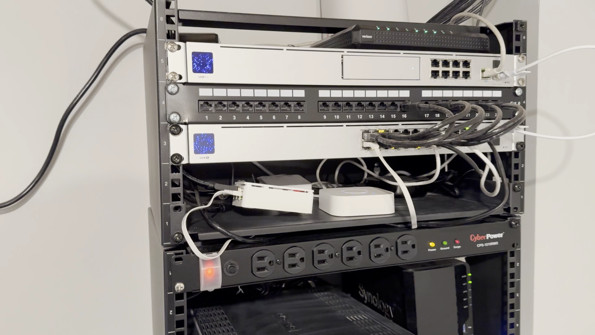
This is a follow-up to an earlier video that I released where I went through my entire Ubiquiti UniFi network for faster home internet, including my complete setup and cost. Now, we’ll look at how (and why) I made my home network more secure using VLANs and firewall rules.
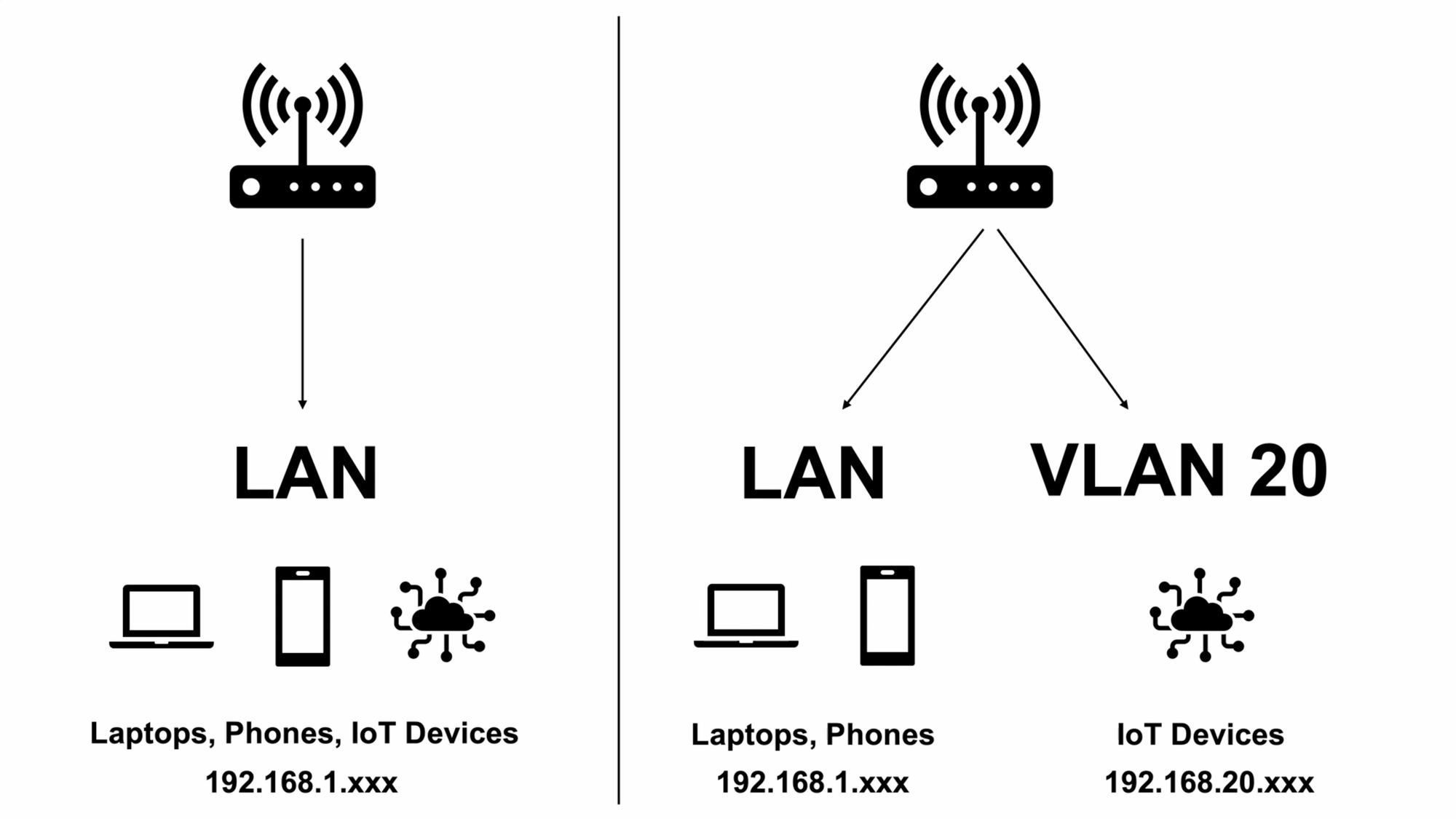
But, what is a VLAN? VLAN stands for Virtual Local Area Network. With one LAN, all of your devices are grouped together, and each device has its own IP address within the the same subnet so the devices can talk to each other and make requests. With VLANs, each is given an ID or a tag, which logically groups a network of devices together in their own subnet regardless of the physical network they are connected to.
One of the reasons for using VLANs in a home environment is to create a more secure home network. For example, you can group all of your IoT, or Internet of Things, devices, like a smart garage door controller that speaks to the cloud, into one VLAN, and separate those IoT devices from the devices on your main LAN, like smartphones and laptops. If someone hacked the IoT device’s cloud service, that could be an entry point to the IoT device on your network, and then the hacker could potentially see the computers on your network. By separating devices using VLANs, you can mitigate this risk.
Another reason for using VLANs may be to simply organize the devices on your network.
Understanding Firewall Rules
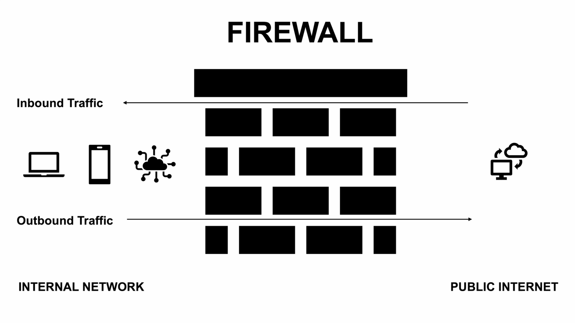
VLANs on their own aren’t as useful from a security standpoint unless you impose traffic and firewall rules. Firewall rules are logical controls that determine which types of traffic are allowed in and out of the network — which are accepted, and which are dropped. I can use firewall rules to decide what my IoT devices are allowed to communicate with, and what can communicate with them. Such rules also ensure that things like my Home Assistant server and Sonos speakers continue to function correctly.
Device Types
So far, I’ve been talking about IoT devices, but let’s take a closer look at device types since it may influence how you want to structure your network.
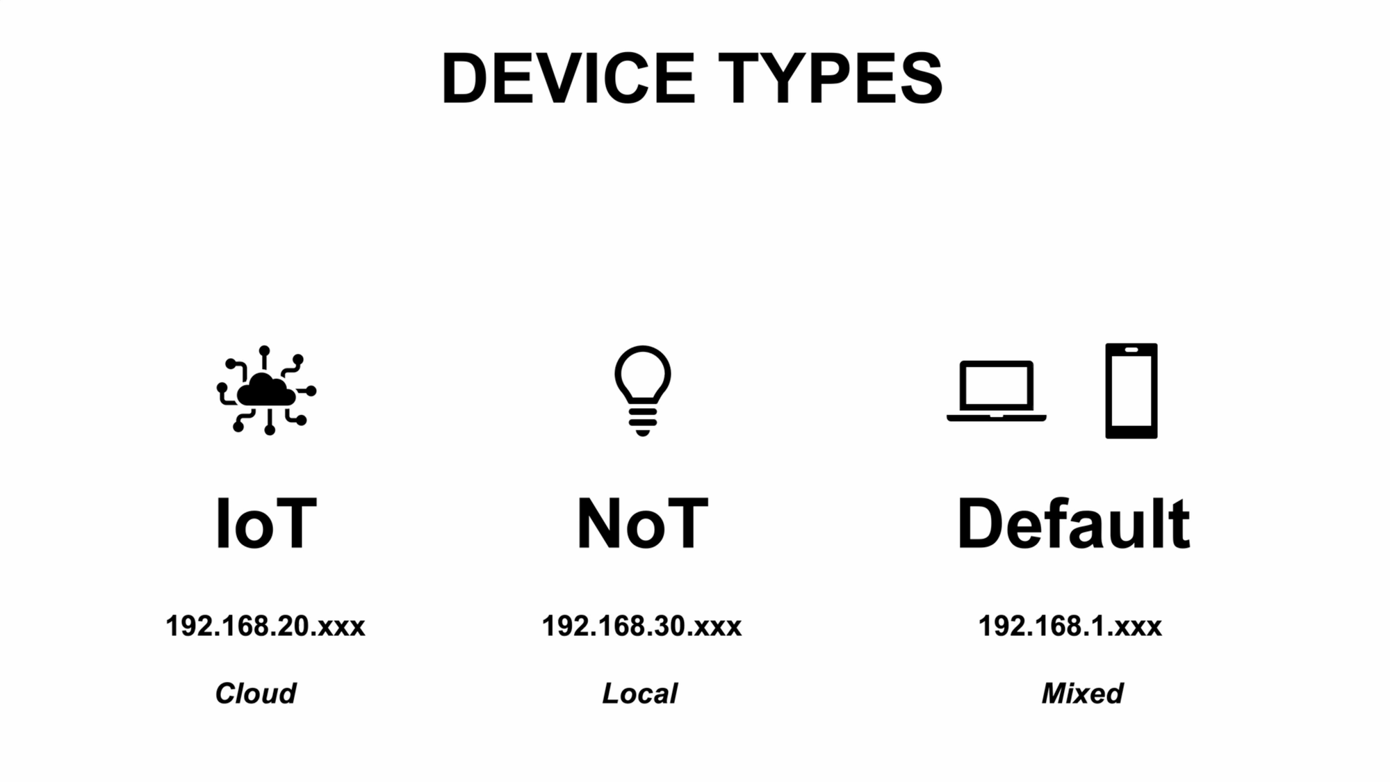
Another example of an IoT device is a smart lock that uses the cloud to send and receive commands. This allows me to control the lock when I’m away and outside my home network. So, the smart lock falls into the category of an IoT device. I need it to talk to the internet, but I don’t need it talking to all of the other devices on my network.
Another type of device in your smart home may be one that only talks locally to your home automation server, but doesn’t require an internet connection to function. This group of local only devices is sometimes referred to as NoT, or Network of Things. Like IoT, the NoT devices don’t need to talk to each other — just to my home automation server, Home Assistant. In general, I prefer local only devices over cloud-based devices, where possible.
It’s not strictly necessary to create separate VLANs for IoT and NoT devices — at the moment I do not purely out of convenience — but you may want to do so. Generally, the more specific you are with your home network setup, the more secure it can be.
Aside from IoT and NoT, I have all of our phones and laptops on the main, or default, LAN. I also have our security cameras on the default LAN, which I’ll address later in this video.
Approach
Before we dive in to how to setup VLANs and firewall rules, a few things to note. I am not a network administrator. Configuring VLANs and firewall rules can be complicated. If you want to deep dive on this subject, checkout Crosstalk Solutions, The Hookup, or Techno Tim. I am sharing the steps that I took to secure and organize my network, since there was no one guide out there that was tailored for my exact setup, which includes:
- Ubiquiti UniFi networking gear
- Home Assistant server for smart home automations
- Sonos speakers
- Amazon Echo devices
- And more
I’ll show you the steps that worked for me, and broadly speaking what may work for you. But before implementing my recommendations, you should consider the exact device setup and needs for your smart home and device environment. I will take you step-by-step through how to create VLANs and firewall rules using a UniFi Dream Machine Pro. This will look different if you’re using different equipment. Even if you are using UniFi, it may look different since they frequently change the user interface.
Let me give you the big picture, then I’ll go through all the steps:
- I’m going to create a VLAN to separate the IoT devices on my network.
- Then, I’ll create firewall rules to govern what type of traffic is accepted and dropped.
- Finally, I’ll assign the various WiFi SSIDs in my home to specific networks — the default LAN and IoT — so that each device starts following the VLAN and firewall rules that I created.
Creating VLANs
To start, I’m going to create a virtual network within my physical network for the IoT class of devices.
Go to Settings, Networks, then click New Virtual Network. I’ll use IoT for the network name. For the subnet host address, we’ll use 192.168.20.1, and 24 for the netmask. 192.168.20.1 is the gateway each device will use to get to another subnet. 24 means that the 192.168.20 portion will be the same for the entire subnet, since 192, 168, and 20 are 8-bit numbers. The last 8 bits, or .1, will vary for each device. The 24 determines how many IP addresses will be available on that subnet.
For the VLAN ID, we’ll use 20, which corresponds to the 20 in the subnet, and helps keep things organized. I’ll enable Multicast DNS, but leave IGMP Snooping disabled on the IoT network. IGMP Snooping pertains to multicast communications, and which devices may want certain types of messages. If you want all the multicast data from the IoT network to be repeated on other VLANs, then you’ll want to disable IGMP Snooping on the IoT network. I’m not going to go into the details of unicast vs. multicast vs. broadcast, but this setting is something you may want to experiment with depending on your devices.
When you’ve configured it as you’d like, hit add. If you wanted a separate VLAN for your NoT devices, you would repeat these steps, but use 192.168.30.1, with 30 for the VLAN ID.
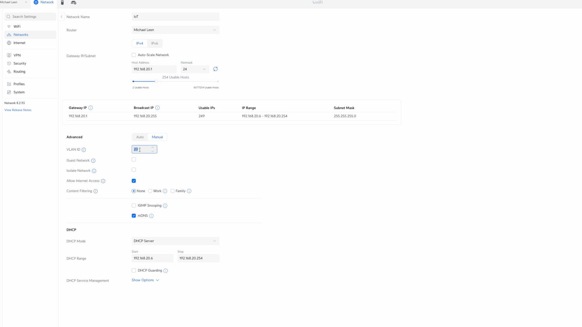
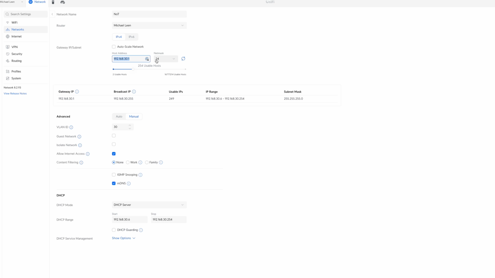
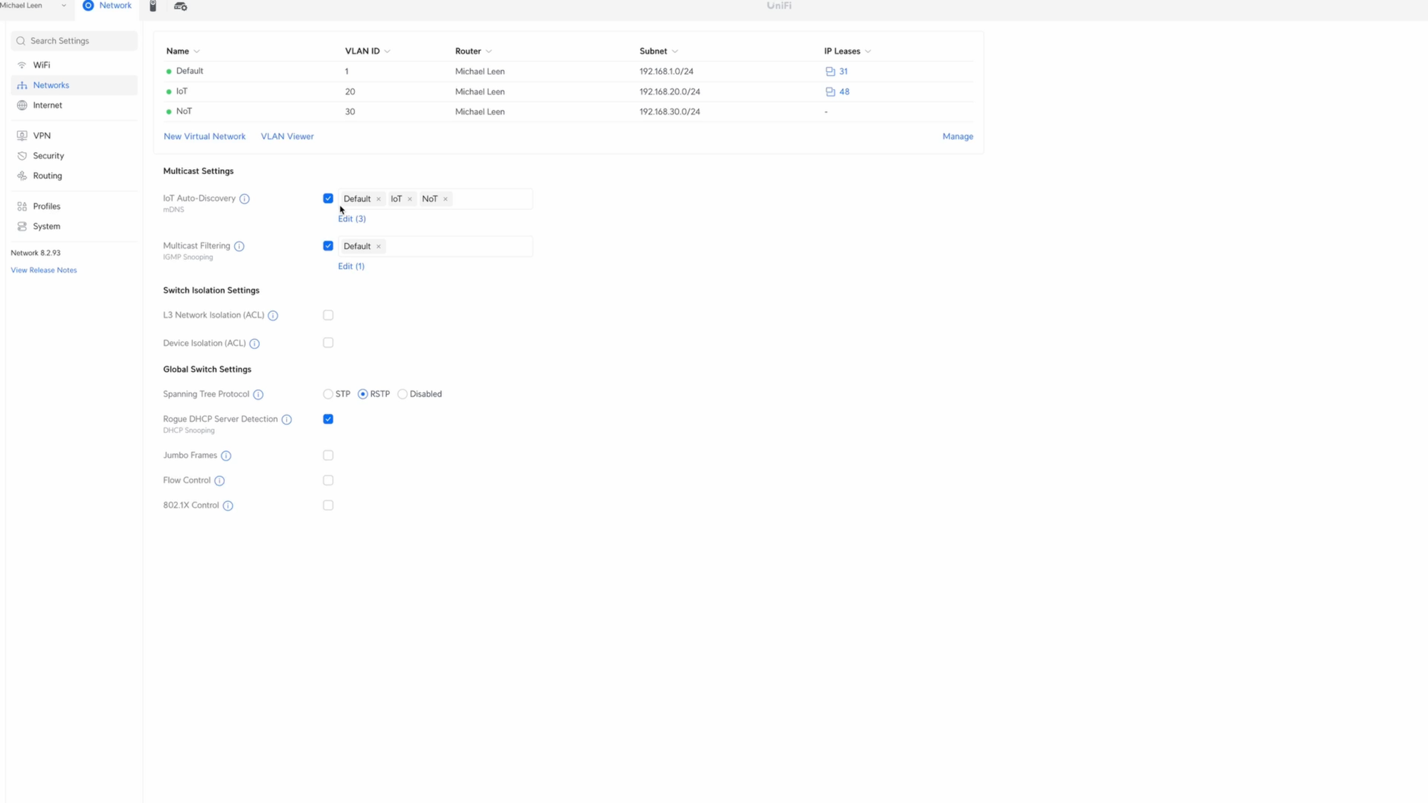
Creating IoT and NoT networks in UniFi.
Creating Firewall Rules
Next, we’re going to create firewall rules that allow and drop certain traffic across the network.
Go to Settings, Security, then click Traffic & Firewall Rules. I’ll start by adding the “allow” rules, and then create the “drop” rules. This is because firewall rules are imposed from top to bottom in the UniFi controller, so the order does matter. If something is allowed at the top, then it won’t be examined against another rule further down. Your networking controller may work differently.
The firewall rules that I am setting up are designed for the devices in my home, including a Home Assistant server, Sonos speakers, and Amazon Echo devices. If you use other devices, you’ll need to determine the correct configuration and ports required.
Allow Rules
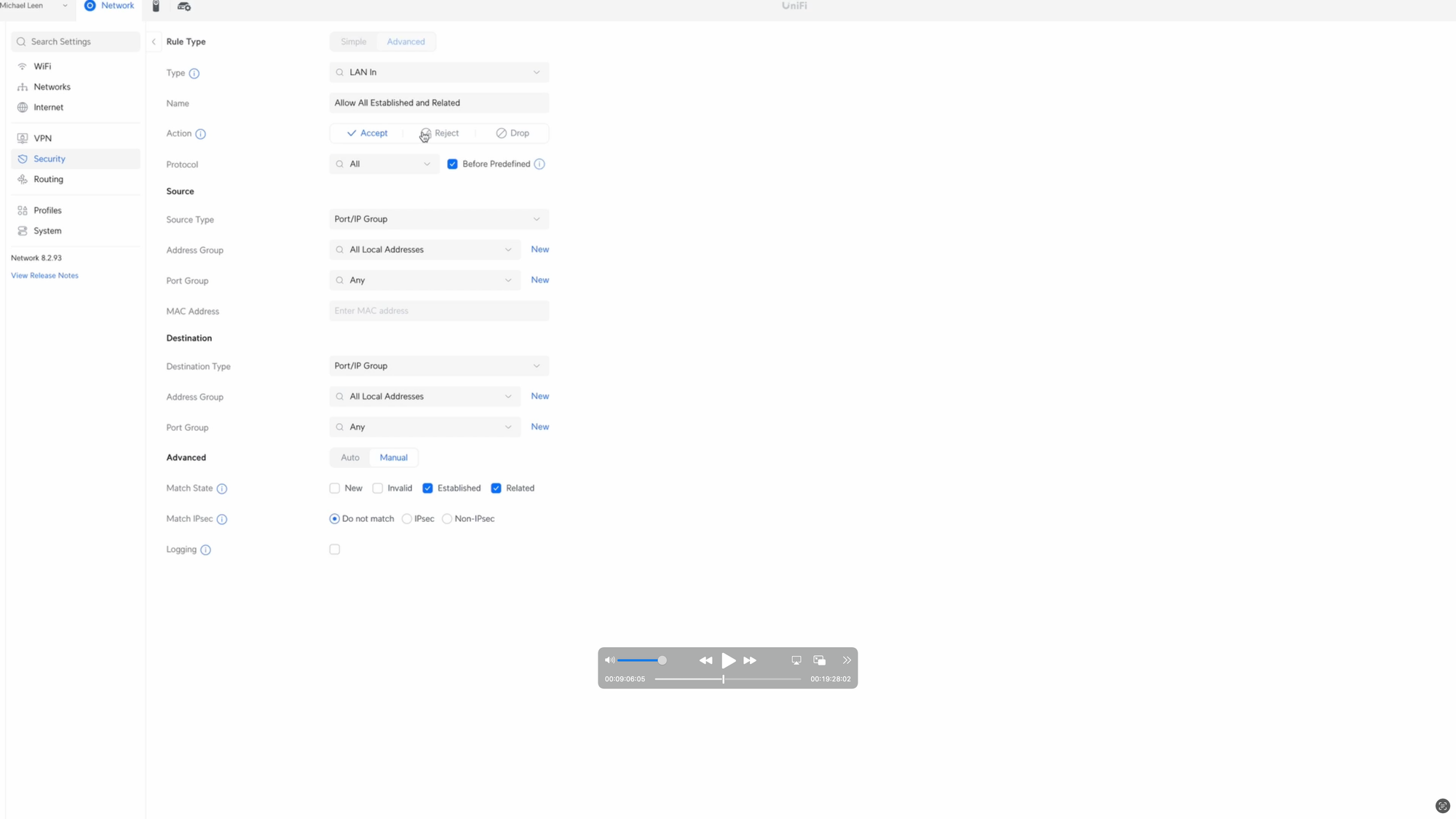
Okay, let’s get started with the first rule, which is to allow all established and related traffic. Broadly speaking, this means that one device can respond to another device when data is requested from it. Click Create Entry, choose LAN In for the type, and I’ll give it the name Allow All Established and Related. Choose Accept for the Action, all protocols, and check Before Predefined.
For the Source, click New next to Address Group. I’ll give this the name All Local Addresses, and then add each local address for my setup under the IPv4 Address/Subnet. For me, this is 192.168.1.0/24, 192.168.20.0/24, and 192.168.30.0/24. The first is for my main LAN, the second is for the IoT network, and the third is for an NoT network, though I’m not actively using that one at the moment. Click Create when you’re done. Then, select the group you just created, All local Addresses, in the Source Address Group.
For the Destination, we’ll also select All Local Addresses. Under Advanced, check the boxes for Established and Related. When you’ve set it up as you’d like, click Add Rule.
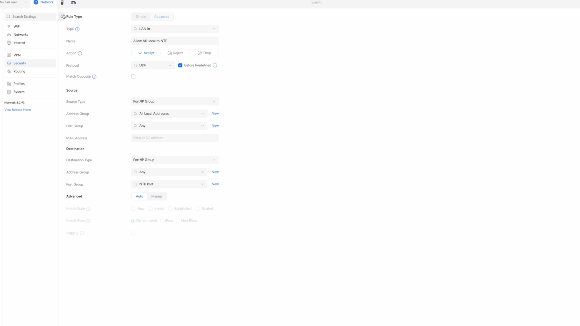
Time to create the next rule, this time for the Network Time Protocol, or NTP, which allows devices to get the correct time. Without this, some devices may stop working. Click Create Entry, choose LAN In for the type, and give it the name Allow All Local to NTP. Choose Accept for the Action, select UDP for the protocol, and check Before Predefined.
For the Source, select All Local Addresses in the Address Group.
For the Destination, click new next to Port Group. I’ll give it the name NTP Port, and add port 123. Click create, and then select NTP Port for the Port Group. When you’re done, click Add Rule.
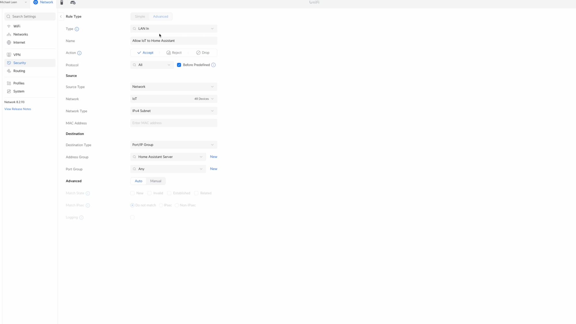
Now, I’ll create a rule that allows the devices on the IoT network to communicate with the Home Assistant server. This is only necessary if you have the same home automation server.
Click Create Entry, choose LAN In for the type, and give it the name Allow IoT to Home Assistant. Choose Accept for the Action, all protocols, and check Before Predefined. Select Network for the Source Type, and select the IoT network that we created earlier.
For the Destination, click New next to Address Group, and give it the name Home Assistant Server. Add the IP address of your Home Assistant server, and click Create. You could just enter the IP address without creating a Home Assistant Server group, but group names are clearer and keep me organized. Select Home Assistant Server from the Address Group dropdown in Destination, then click Add Rule.
Any time you add a device IP to one of these groups, you should set a fixed IP address for that device to ensure it remains the same, and thus continues to work with your firewall rules. To do this, go to Client Devices, click the device, then Settings, and select Fixed IP Address.
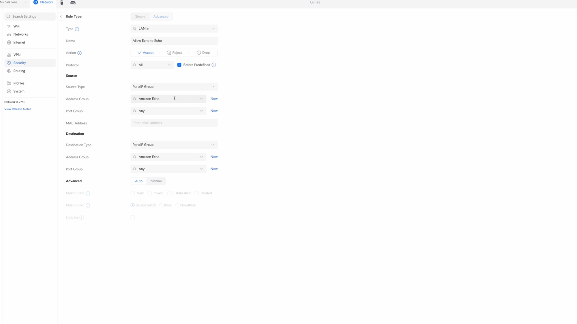
Next, we’ll create a rule to ensure the Amazon Echo devices on the IoT network can talk to one another, which is useful for things like synchronized, multi-room audio.
Click Create Entry, choose LAN In for the type, and give it the name Allow Echo to Echo. Choose Accept for the Action, all protocols, and check Before Predefined.
Click New next to Source Address Group. I’ll give it the name Amazon Echo, add each IP address of the Echo devices, and click Create. Make sure you set a Fixed IP address for each of the Echo devices. Select Amazon Echo from the Address Group dropdown for the Source, and select it again in the Address Group for the Destination. Then click Add Rule.
Now, we’ll create a rule to ensure casting devices on the default LAN, like smartphones, can talk to Sonos speakers. This requires opening up specific ports.
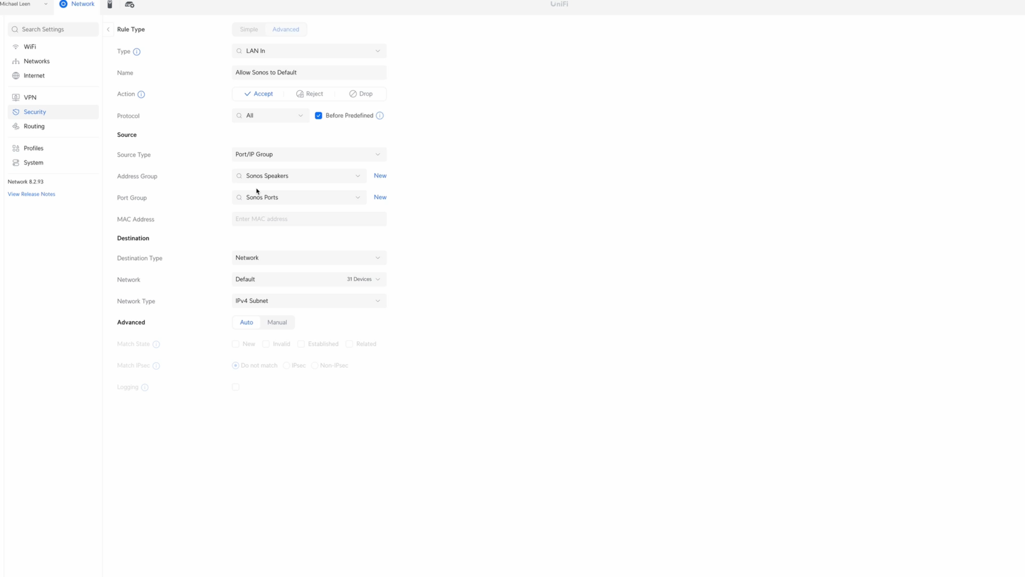
Click Create Entry, choose LAN In for the type, and I’ll give it the name Allow Sonos to Default, with Default being the name of my main LAN. Choose Accept for the Action, all protocols, and check Before Predefined.
Click New next to Source Address Group. I’ll give it the name Sonos Speakers, add each IP address of the Sonos speakers, and click Create. Once again, you should set each Sonos speaker to a fixed IP address. Select Sonos Speakers from the Source Address Group. Click New next to the Source Port Group, and create a port group called Sonos Ports. Then, add all the ports that Sonos uses, which I’ll link to in the video description. Once ready, click Create. Then select Sonos Ports for the Source Port Group.
For the Destination, select Network, and then Default, which is the main LAN, since that’s where I have the devices that I cast from, like smartphones and laptops. When done, click Add Rule.
Drop Rules
At this point, I’ve created all of the Allow rules for my setup. To make my network more secure, I’m going to add broad Drop rules at the bottom of my firewall rules.
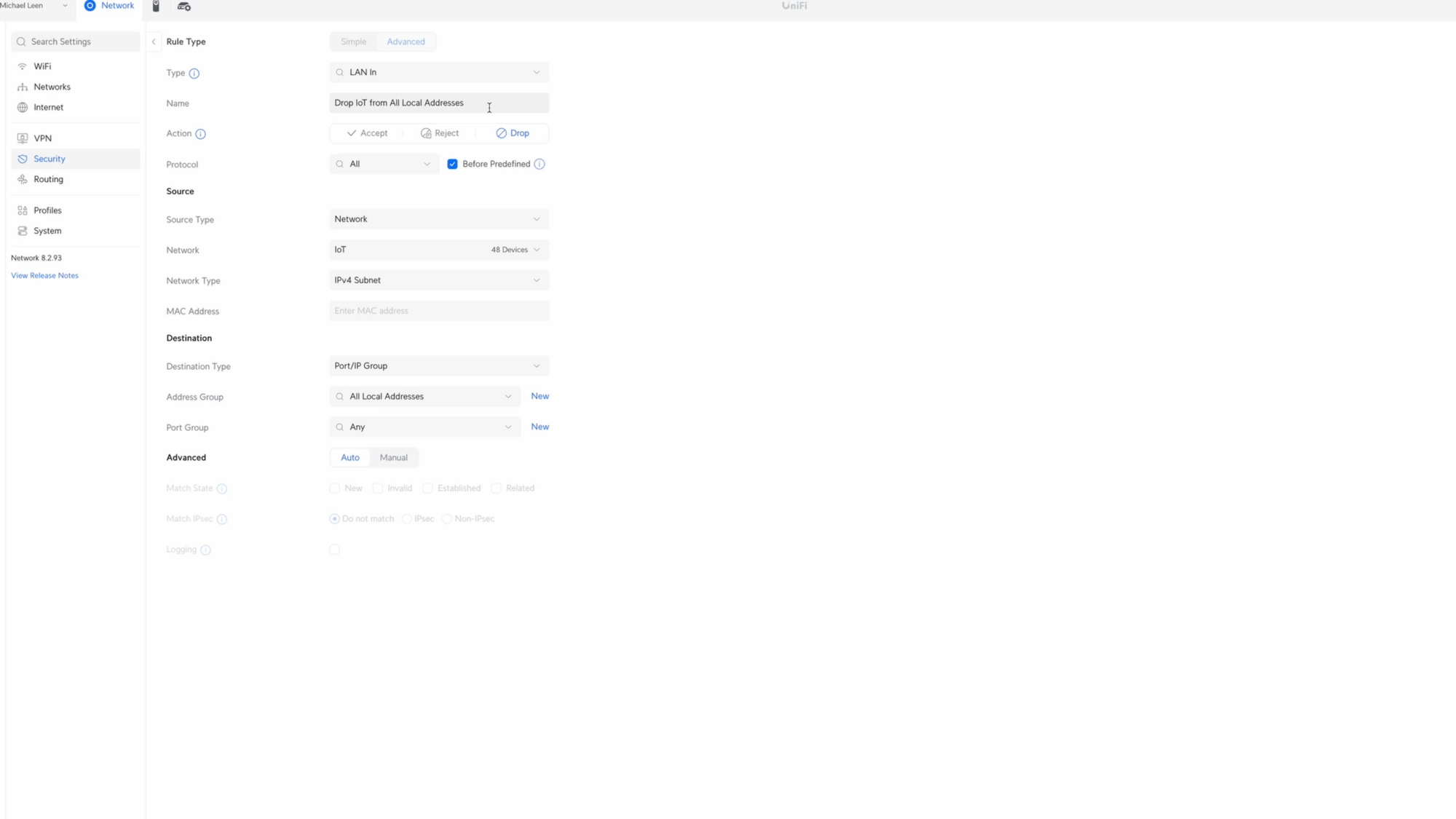
We’ll start with a rule to drop all IoT devices from communicating with devices on my local network. Click Create Entry. I’ll give it the name, Drop IoT from All Local Addresses. Choose Drop for the Action, all protocols, and check Before Predefined.
For the Source, select the IoT network. For the Destination Address Group, select All Local Addresses, which I created earlier. Then click Add Rule.
The next Drop rule is for security cameras. As mentioned, my security cameras are on my default LAN. It may seem odd to keep cameras on the default LAN, but there can be performance degradation when routing the traffic from, in my case, 11 security cameras across virtual networks.
To function, each camera talks to the Network Video Recorder, or NVR, for camera stream requests. There is no need for a device outside my network to start the camera stream, or for the camera itself to start that connection with another device. I can regulate this by denying the cameras’ outbound traffic using firewall rules.
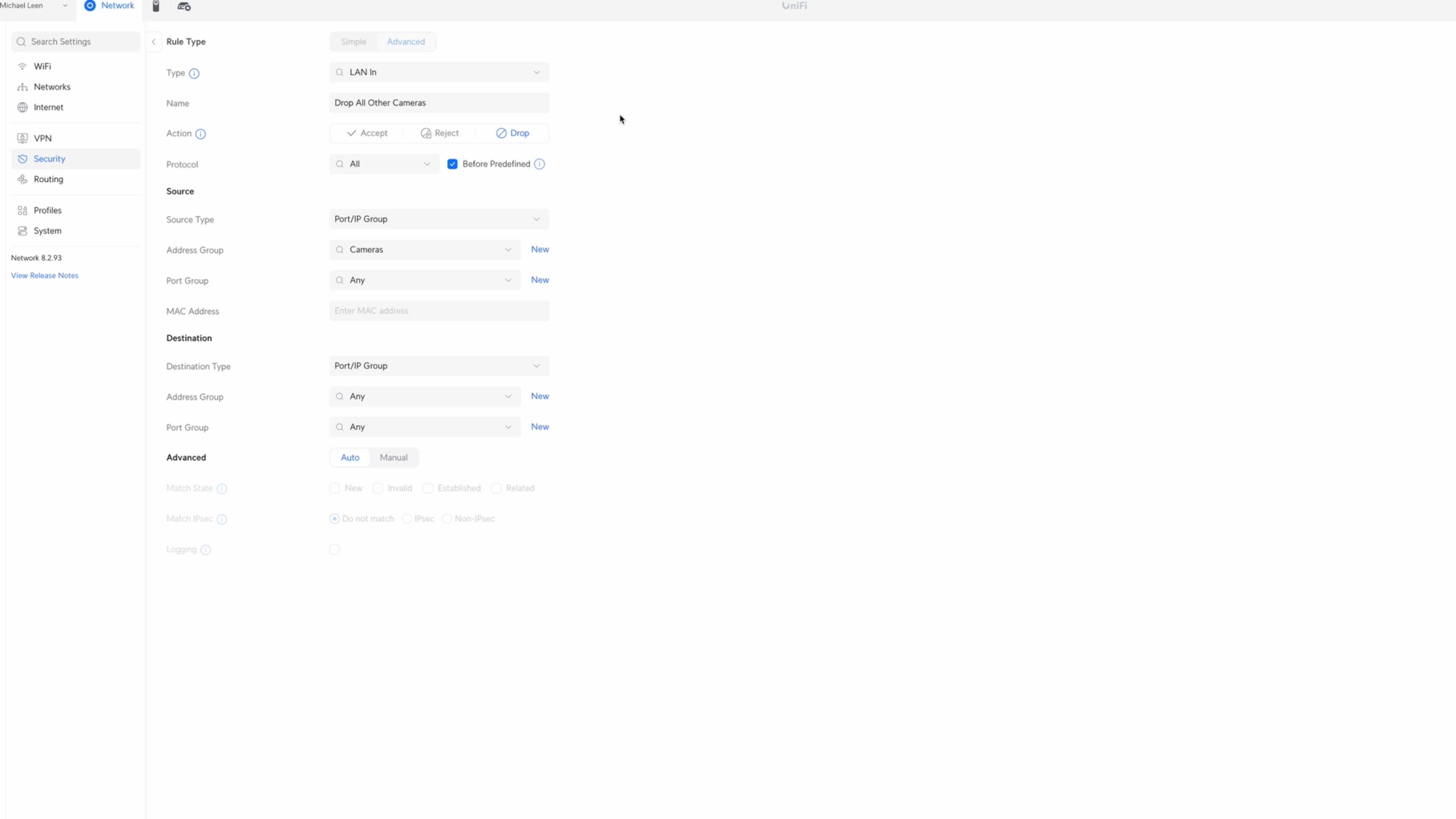
Click Create Entry. I’ll give it the name Drop All Other Cameras. Choose Drop for the Action, all protocols, and check Before Predefined. Click New next to the Source Address Group. I’ll give it the name Cameras, and then add the IP address for each of the cameras on my network. Then click Create. I also set each camera to a fixed IP address. Select Cameras for the Source Address Group, and for the Destination, you’ll use Any address and Any port.
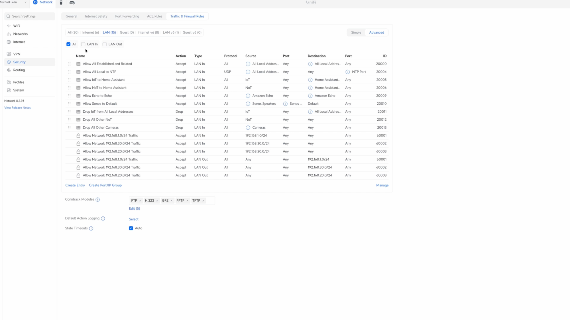
Alright, that’s it for the Allow and Drop firewall rules for my setup. If you watched the YouTube video, you may have noticed that there are several other firewall rules listed. A couple refer to an NoT network that I created, but am not currently using. The idea is that I could separate IoT devices that require an internet connection to function, like my Wi-Fi water heater controller, from NoT devices that do not, like an ESPHome device.
The additional firewall rules with the lock icon were created automatically by the UniFi controller. This may be different depending on the system you are using.
WiFi
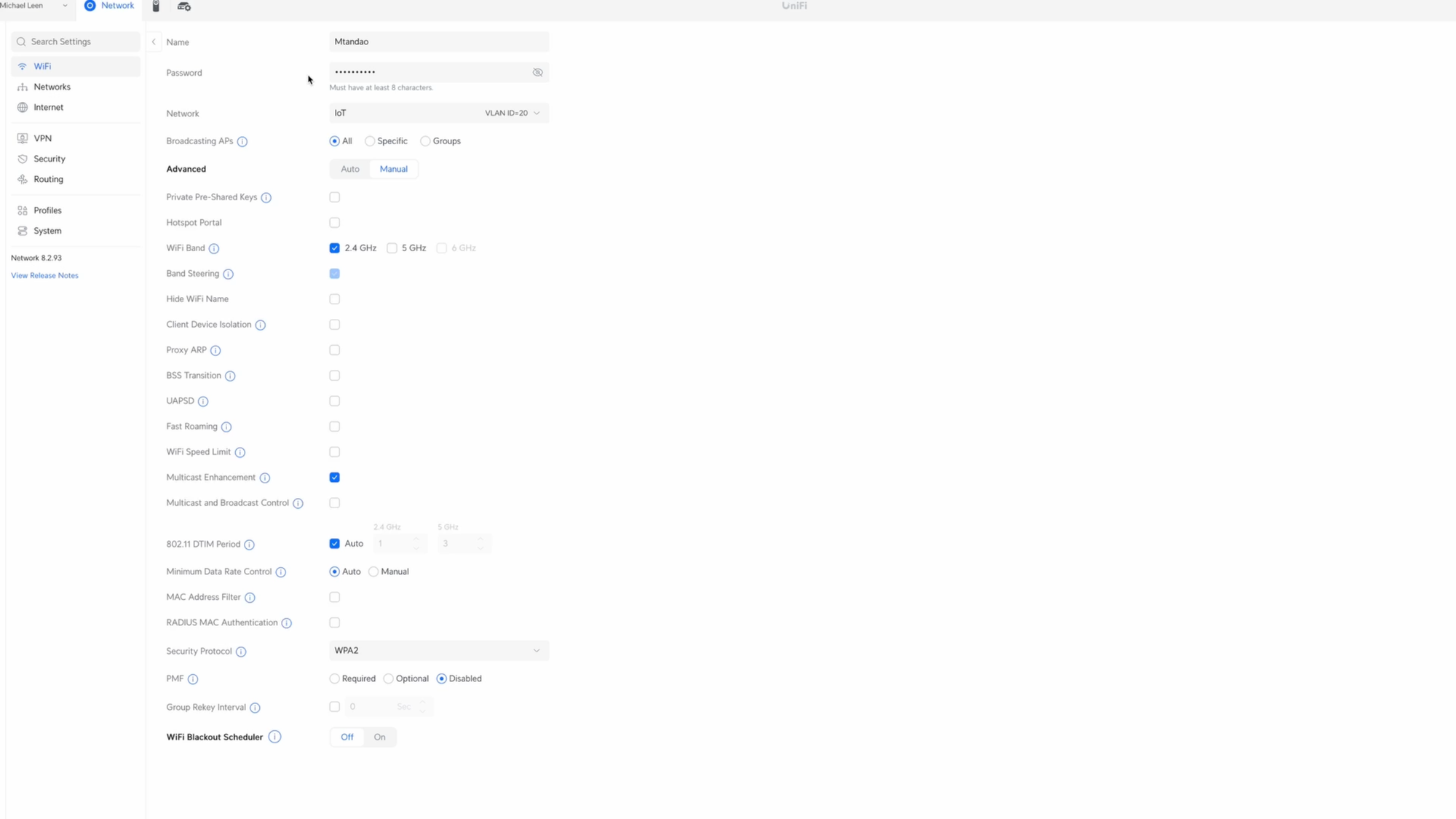
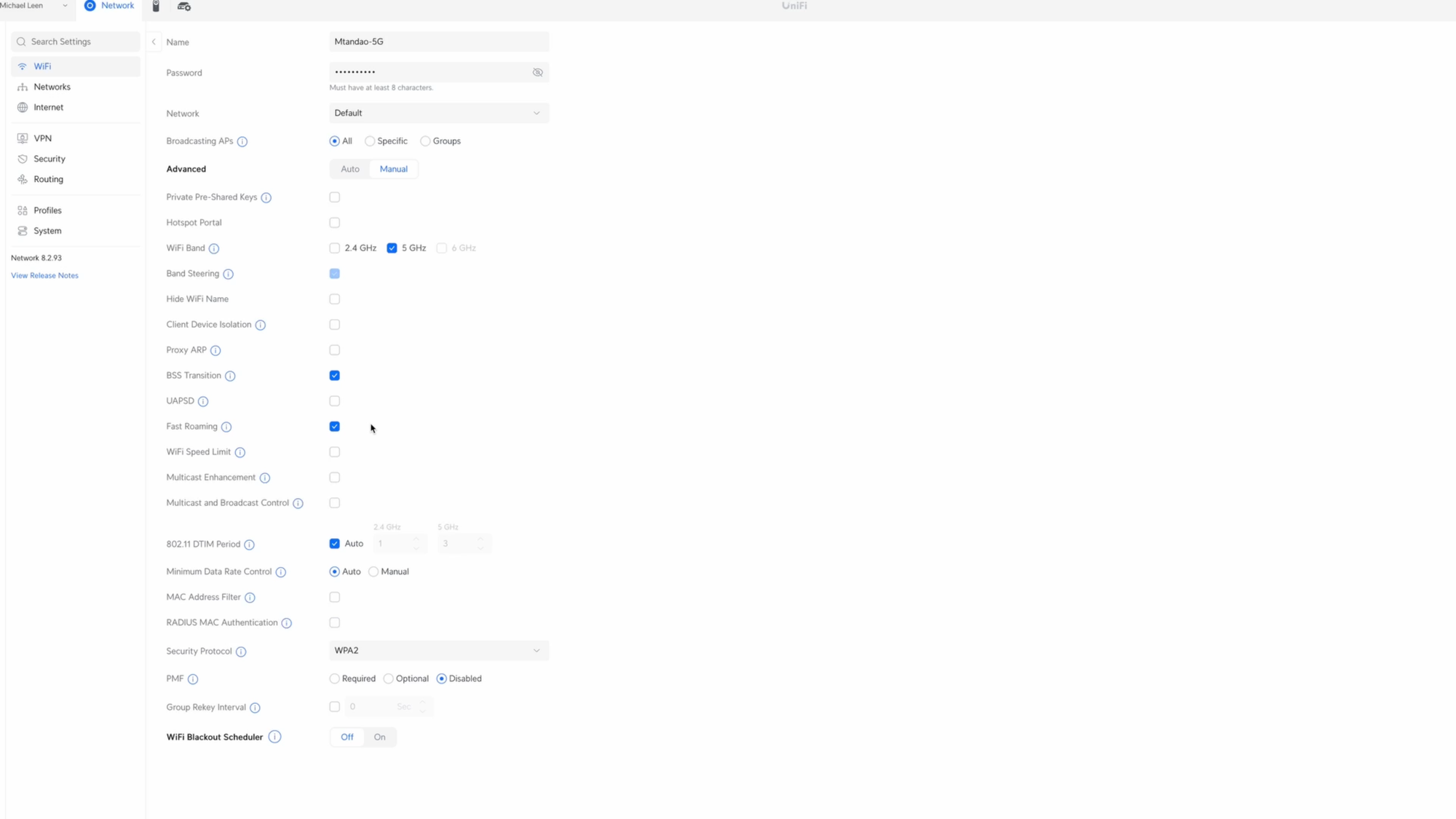
In order to get devices onto the correct VLAN and following the firewall rules, I need to adjust the WiFi settings. I have separate WiFi SSIDs for my IoT devices and default LAN. Each network uses only the 2.4Ghz or 5Ghz band, but not both. All of my IoT devices are on the 2.4Ghz WiFi SSID, whereas my main devices, like phones and laptops, are on the 5Ghz WiFi. I allow each WiFi SSID to broadcast on all my access points, but you may prefer something else.
Let’s take a closer look at my configuration, starting with the WiFi for my IoT devices. I assign this to the IoT network that we created earlier, which corresponds to VLAN ID 20. Under Advanced and Manual, I have it set to only use the 2.4Ghz WiFi band, which is what IoT devices typically use. Since my IoT devices tend to be fixed in place, the only other setting I have enabled is Multicast Enhancement.
Taking a look at the WiFi for devices on the default LAN, the setup is a bit different. Here, I’m only using the 5Ghz WiFi band, and I have checked BSS Transition and Fast Roaming, since devices on my main LAN, like smartphones and laptops, move around regularly.
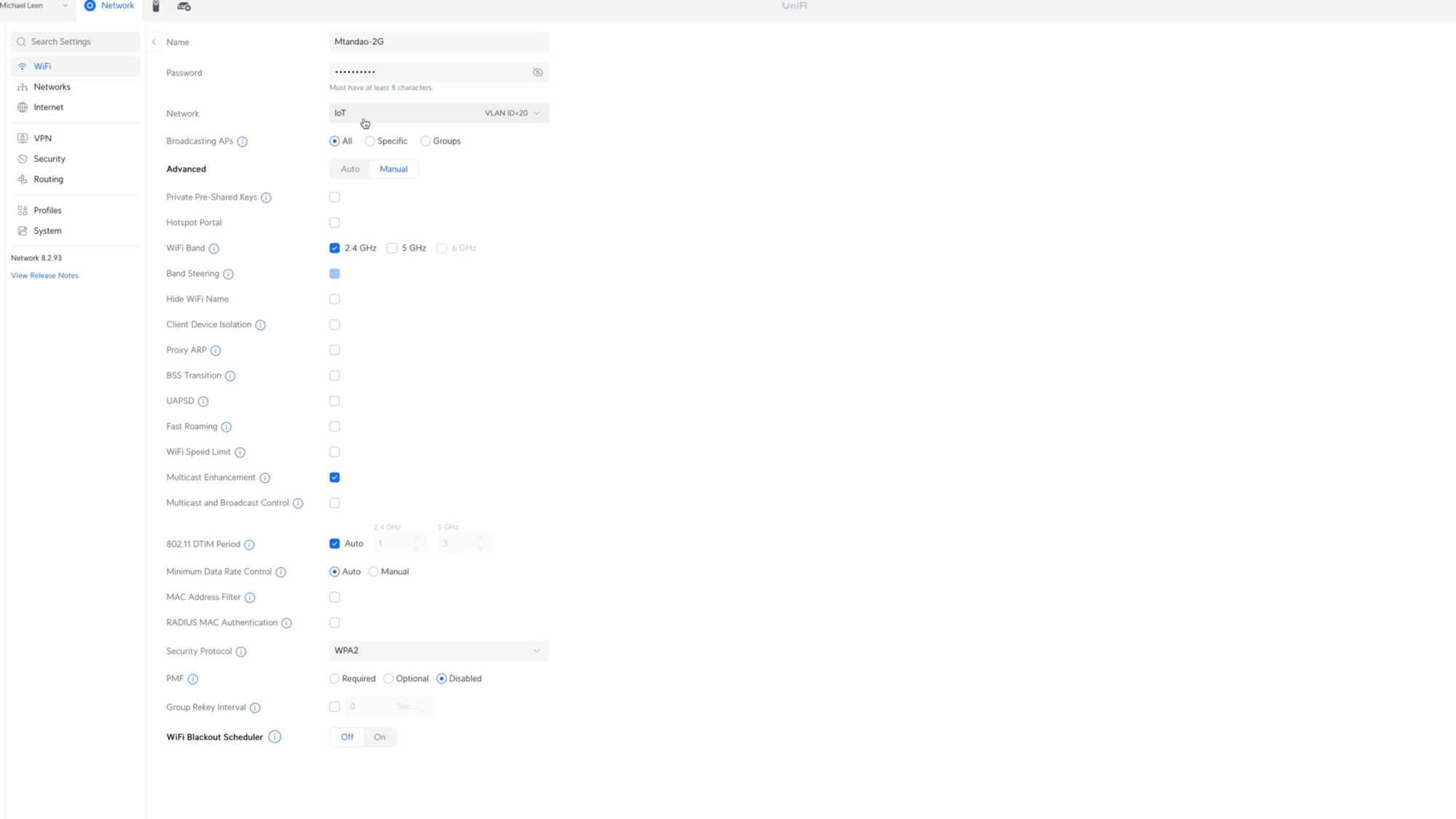
I do have a another WiFi SSID exclusively for the Sonos speakers on my IoT network, because in my experience, separating Sonos speakers like this improves their reliability.
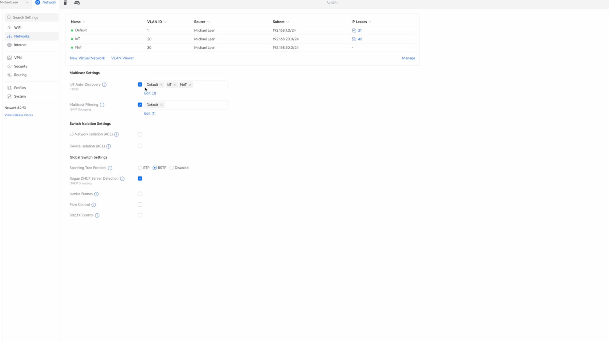
Finally, I have Multicast DNS enabled on all of my networks, but I only have IGMP Snooping enabled on the Default, or main LAN.
Final Thoughts
If you followed along and made it this far, you have made your network more secure by isolating IoT devices on their own VLAN, and using firewall rules to allow or drop certain types of traffic.
Of course, you can do even more to secure your network, including VPNs and port security, but that is beyond the scope of this tutorial.
Watch on YouTube
Featured Tech
UniFi Dream Machine SE: https://amzn.to/3ItK0lt
UniFi Dream Machine Pro: https://tinyurl.com/32hjk7e8
UniFi Standard 24-Port Switch: https://amzn.to/3Iv2z8Z
UniFi Lite Access Point: https://amzn.to/49M3xJR
UniFi U6 Lite Access Point: https://tinyurl.com/ywb6kxrr
UniFi U6 Long Range Access Point: https://amzn.to/49M4ems
UniFi U6 In Wall Access Point: https://amzn.to/3T8IUR6
CyberPower Rackmount Surge Protector: https://amzn.to/3T8j3IZ
CyberPower USP (battery backup): https://amzn.to/3IxUpwF